Air quality management is a critical concern in industrial environments where pollutants such as carbon monoxide (CO), volatile organic compounds (VOCs), and excessive heat can pose serious health risks to workers and compromise production efficiency. Poor air quality can lead to reduced worker productivity, equipment malfunctions, and even regulatory violations. Implementing an effective ventilation system ensures a safer, more compliant, and efficient workspace.
The Role of IoT and Automation in Smart Factory Environments
The integration of Internet of Things (IoT) technology in smart factories has revolutionized industrial automation by enabling real-time monitoring, predictive maintenance, and autonomous control systems. IoT-based smart ventilation systems continuously collect and analyze environmental data, allowing factories to optimize energy usage and respond dynamically to hazardous conditions without human intervention. Through connected sensors and automated actuators, factories can maintain an ideal working environment while ensuring regulatory compliance.
Overview of the Smart Factory Ventilation System Project
GitHub Repository
This project demonstrates the design and implementation of an IoT-enabled Smart Factory Ventilation System that monitors and regulates air quality in real-time. The system consists of:
- MCU1 (Sensor Node): Continuously collects temperature and CO levels from the environment.
- Cloud Server: Processes sensor data, visualizes it through real-time graphs, and determines whether intervention is required.
- MCU2 (Actuator Node): Receives commands from the cloud and controls the fan and window to mitigate hazardous air conditions.
By simulating this system using Python Sockets, Cisco Packet Tracer, and Matplotlib, the project replicates a real-world industrial ventilation solution with live data visualization and automated environmental control.
What This Blog Post Will Cover
This blog post will walk you through:
- Understanding the Problem Statement – The need for smart ventilation in industrial settings.
- Technology Stack and Tools Used – An overview of the programming languages, software, and hardware employed in this project.
- System Architecture and Workflow – A breakdown of how the different components interact.
- Implementation Details – Step-by-step execution of the cloud server, sensor node, and actuator logic.
- Challenges Faced and Solutions Implemented – Key obstacles encountered during development and how they were addressed.
- Testing and Results – Observations on the system’s performance and effectiveness.
- Future Enhancements – Suggestions for improving and scaling the system.
By the end of this post, you will have a complete understanding of how to design and implement an IoT-based smart ventilation system from scratch, leveraging cloud computing, real-time data visualization, and automated environmental control.
Understanding the Problem Statement
Why is a Ventilation System Necessary in Industrial Environments?
Industrial settings often involve processes that generate hazardous gases, excessive heat, and airborne contaminants. Poor ventilation can lead to serious health risks for workers, such as respiratory illnesses and reduced cognitive function due to exposure to high levels of carbon monoxide (CO) and other pollutants. Additionally, improper air circulation can cause overheating of equipment, leading to inefficiencies, malfunctions, or even fire hazards. Implementing an automated ventilation system ensures a safe, compliant, and energy-efficient work environment.
What Parameters Need to Be Monitored?
To maintain air quality and prevent hazardous conditions, two key parameters are continuously monitored:
- CO Levels: Carbon monoxide is a colorless, odorless gas that can be lethal at high concentrations. Monitoring CO levels ensures that workers are not exposed to unsafe conditions.
- Temperature: High temperatures can lead to overheating of machinery and discomfort for workers. Controlling temperature within an optimal range enhances productivity and prolongs equipment lifespan.
The Role of MCU1 (Sensor Unit) and MCU2 (Actuator Unit)
The system relies on two microcontroller units (MCUs) for monitoring and control:
- MCU1 (Sensor Unit): This device is responsible for continuously reading CO levels and temperature from the environment. It then transmits the data to the cloud server at regular intervals.
- MCU2 (Actuator Unit): Based on commands from the cloud server, this unit controls the fan and window actuators to either increase ventilation or maintain the current state, ensuring air quality remains within safe limits.
How a Cloud-Based Server Facilitates Real-Time Monitoring and Automation
The cloud server acts as the central intelligence of the system. It performs the following functions:
- Receives sensor data from MCU1 at defined time intervals.
- Processes and analyzes the data to determine if CO levels or temperature exceed safe thresholds.
- Sends control commands to MCU2 to adjust ventilation systems accordingly.
- Visualizes real-time sensor readings using an interactive dashboard, providing insights into system performance and environmental conditions.
Real-World Applications of Such a System
Automated ventilation systems using IoT technology have applications across various industries:
- Manufacturing Plants: Ensuring worker safety in environments where toxic fumes or excessive heat are common.
- Mining Industry: Detecting and mitigating CO exposure to prevent fatalities in underground tunnels.
- Data Centers: Managing airflow and temperature to prevent overheating of critical IT infrastructure.
- Automotive Workshops: Controlling emissions from vehicle exhausts to protect mechanics from harmful gas exposure.
- Warehouses and Cold Storage Facilities: Regulating air quality and temperature to maintain product integrity and compliance with health standards.
By implementing this Smart Factory Ventilation System, industrial facilities can significantly improve worker safety, operational efficiency, and regulatory compliance while reducing energy consumption through automated control mechanisms.
Technology Stack and Tools Used
A. Programming and Software
1. Python
Python is used for server-side communication and real-time data visualization. The cloud server processes sensor data, sends control commands, and visualizes the results using Python.
2. Cisco Packet Tracer
Cisco Packet Tracer is employed to simulate IoT devices and networks, allowing the creation of virtual microcontrollers (MCU1 & MCU2) that interact with sensors and actuators.
3. Matplotlib
Matplotlib is used for real-time data visualization by plotting CO levels, temperature, and system status updates dynamically.
B. Hardware and Sensors (Simulated in Packet Tracer)
1. CO Sensor
Since Packet Tracer does not include a dedicated CO sensor, a generic environmental sensor is used, and its water level readings are mapped to CO levels for simulation purposes.
2. Temperature Sensor
A standard temperature sensor is integrated into the system to measure ambient temperature and report readings to the cloud.
3. Microcontroller Units (MCU1 & MCU2)
- MCU1 (Sensor Unit): Captures CO and temperature readings and sends data to the cloud.
- MCU2 (Actuator Unit): Receives commands from the cloud and controls the fan and window actuators based on sensor readings.
4. Fan & Window Actuators
These components regulate airflow based on cloud commands, helping to reduce CO levels and maintain optimal temperature.
C. Communication Protocols
1. TCP/IP Sockets for Real-Time Data Transmission
TCP sockets are implemented to ensure reliable, real-time communication between the cloud server and MCUs.
2. Structured Data Messages Between Devices
Data is transmitted using a structured message format to ensure efficient parsing and processing by the cloud and MCUs.
System Architecture and Workflow
A. Overview of the System Components
The Smart Factory Ventilation System consists of multiple components working together to monitor and regulate air quality in real-time. The primary components include the Cloud Server, MCU1 (Sensor Unit), and MCU2 (Actuator Unit). Each plays a critical role in ensuring efficient operation.
1. The Role of the Cloud Server
The cloud server serves as the central processing unit of the system, responsible for:
- Receiving real-time sensor data from MCU1.
- Processing the collected data and checking against predefined thresholds.
- Making decisions on whether to activate ventilation mechanisms.
- Sending control commands to MCU2 for corrective actions.
- Displaying live sensor readings and system status using a graphical dashboard.
2. How MCU1 Collects Sensor Data and Sends It to the Cloud
- MCU1 is equipped with CO and temperature sensors that continuously monitor environmental conditions.
- At regular intervals, MCU1 reads the CO level and temperature and formats the data into structured messages.
- This data is transmitted to the cloud server using TCP/IP communication.
- The cloud server receives and logs the data for further processing and visualization.
3. How MCU2 Receives Commands from the Cloud and Takes Action
- MCU2 functions as the actuator unit, responsible for controlling the fan and window.
- It listens for control signals from the cloud server.
- When an alert condition is met (elevated CO or temperature levels), the cloud server sends commands to MCU2.
- Upon receiving the command, MCU2 activates the fan and opens the window to restore air quality.
- MCU2 remains active until the sensor readings return to normal, after which the cloud sends a command to turn off the actuators.
B. Data Flow and Decision Making
Step 1: MCU1 Reads Sensor Data
- CO and temperature sensors measure environmental conditions in real-time.
- The collected data is formatted as a structured message and sent to the cloud.
Step 2: Cloud Server Processes Data and Checks Thresholds
- The cloud server receives the data and logs it into the system.
- It compares the sensor readings against pre-defined safety thresholds:
- Temperature Threshold: 35°C
- CO Level Threshold: 20 ppm
Step 3: Cloud Sends Control Commands to MCU2 if Threshold is Exceeded
- If temperature > 35°C or CO > 20 ppm, the cloud triggers an alert state.
- The server sends control commands to MCU2, instructing it to activate the fan and open the window.
Step 4: MCU2 Activates Fan and Opens Window
- MCU2 receives the command and executes the required action.
- The fan turns ON, and the window opens, improving ventilation.
- The system remains in this state until the CO level and temperature drop to safe limits.
Step 5: System Continues Monitoring and Dynamically Adjusts Actuators
- The system continuously monitors sensor readings.
- If the CO and temperature levels return to normal, the cloud sends a shutdown signal to MCU2.
- MCU2 turns OFF the fan and closes the window.
- The process repeats indefinitely, ensuring a safe and controlled environment.
C. System Diagram & Illustration
1. System Diagram
To better understand how data flows through the system, refer to the diagram below:
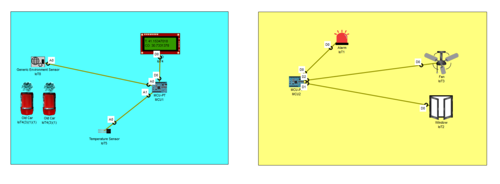
2. Explanation of Key Components with Flowchart
Below is a simplified flowchart showing the logic of the Smart Factory Ventilation System:
- Start → MCU1 collects CO and temperature data.
- MCU1 sends data to the cloud.
- Cloud server checks if readings exceed threshold values.
- If NO → Continue monitoring.
- If YES → Send control command to MCU2.
- MCU2 receives command and activates fan and window.
- Cloud continues monitoring until CO and temperature return to normal.
- Cloud sends a stop signal to MCU2 to turn off fan and close window.
- Repeat monitoring cycle continuously.
This structured approach ensures that the system remains responsive, automated, and effective in regulating air quality in industrial environments.
Implementation: Writing the Code
A. Setting Up the Cloud Server (Python Sockets)
The cloud server is the core of the system, responsible for receiving sensor data, processing alerts, and sending control commands to MCU2. It uses Python’s socket programming to communicate with the sensor (MCU1) and actuator (MCU2).
1. How the Server Listens for Sensor Data
- The cloud server runs a TCP socket server that listens for incoming connections from MCU1 on port 4444.
- It receives sensor readings (temperature and CO levels) as a comma-separated string.
- Data is logged and stored in a dictionary for live visualization.
Relevant Code Snippet:
with socket.socket(socket.AF_INET, socket.SOCK_STREAM) as sensor_socket:
    sensor_socket.bind((HOST, PORT_SENSOR))
    sensor_socket.listen(1)
    conn, addr = sensor_socket.accept()
2. Processing Incoming Data and Triggering Alerts
- The server parses the received data and checks if values exceed safety thresholds.
- If temperature > 35°C or CO > 20 ppm, an alert status is triggered and sent to MCU2.
Relevant Code Snippet:
alert_status = 1 if temperature > TEMP_THRESHOLD or co_level > CO_THRESHOLD else 0
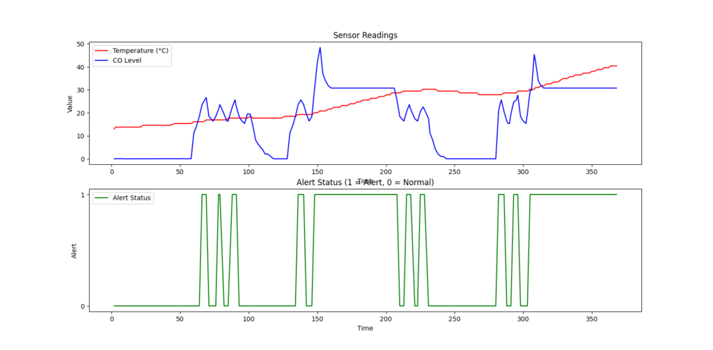
send_alert(alert_status)3. Live Visualization of Sensor Data
- The Matplotlib animation function dynamically updates two live graphs:
- Temperature & CO levels over time
- Alert status (1 = Alert, 0 = Normal)
Relevant Code Snippet:
ani = FuncAnimation(fig, update_plot, interval=500)
plt.show()
B. Writing the MCU1 Sensor Code (Simulated in Packet Tracer)
MCU1 is responsible for collecting environmental data and sending it to the cloud.
1. How MCU1 Reads CO and Temperature Data
- MCU1 reads analog sensor values from two pins (
A0for CO,A1for temperature). - The raw sensor readings are converted into human-readable values:
- Temperature is scaled between -100°C to 100°C.
- CO levels are mapped to ppm (parts per million).
Relevant Code Snippet:
temperature = (analogRead(temperaturePin) / 1023.0) * 200 - 100
CO_level = 2.62 * (analogRead(coSensorPin) / 1023.0) * 100
2. Sending Data to the Cloud Server Using TCP
- MCU1 connects to the cloud server on port 4444 and sends sensor readings as a formatted string.
- The data format is:
timestamp,temperature,CO_level.
Relevant Code Snippet:
if client.state() == 3:
    client.send(str(count) + "," + str(temperature) + "," + str(CO_level))
C. Writing the MCU2 Actuator Code (Simulated in Packet Tracer)
MCU2 receives commands from the cloud and controls the fan and window actuators.
1. Receiving Control Commands from the Cloud
- MCU2 connects to port 5555 to receive ON/OFF commands from the cloud.
- Commands received:
- ‘1’ → Turn ON fan and open window.
- ‘0’ → Turn OFF fan and close window.
Relevant Code Snippet:
if received_data == "1":
    digitalWrite(0, HIGH)
    customWrite(1, '1')
    customWrite(2, '1')
2. Turning ON/OFF the Fan and Opening/Closing the Window
- MCU2 sets GPIO pins HIGH or LOW to control the actuators.
- Actuators remain ON until a ‘0’ command is received from the cloud.
Relevant Code Snippet:
elif received_data == "0":
    digitalWrite(0, LOW)
    customWrite(1, '0')
    customWrite(2, '0')
D. Visualizing Sensor Data Using Matplotlib
1. Setting Up a Live Dashboard with Dynamic Updates
- The cloud server uses Matplotlib’s FuncAnimation to update real-time graphs.
- The dashboard displays:
- Temperature variations over time
- CO level fluctuations
- Alert status (Active/Normal)
Relevant Code Snippet:
def update_plot(frame):
    ax1.clear()
    ax1.plot(sensor_data["time"], sensor_data["temperature"], label="Temperature (°C)", color='r')
    ax1.plot(sensor_data["time"], sensor_data["co"], label="CO Level", color='b')
    ax2.clear()
    ax2.plot(sensor_data["time"], sensor_data["alert"], label="Alert Status", color='g')
2. Graphing Temperature, CO Levels, and Alert Status
- The first graph shows sensor readings (temperature and CO levels).
- The second graph indicates whether an alert is active (
1 = Alert,0 = Normal). - The graph updates every 500 milliseconds, providing a real-time view of the system.
This implementation ensures an automated, responsive, and intelligent ventilation system that monitors and controls air quality dynamically.
Challenges and How They Were Solved
A. Handling Multiple Clients in the Cloud Server
Issue:
Initially, the cloud server could only handle one client connection at a time, limiting scalability and real-time responsiveness. This restriction created bottlenecks in data transmission, preventing efficient monitoring of multiple sensors.
Solution:
The alert server was modified to dynamically open and close connections, enabling multiple clients to interact with the system without conflict. This was achieved by:
- Implementing a multi-threaded server that could handle multiple connections concurrently.
- Ensuring proper session management to prevent dropped connections or data loss.
By implementing these modifications, the server efficiently processed multiple data sources simultaneously, ensuring real-time monitoring without interruption.
B. No Dedicated CO Sensor in Packet Tracer
Issue:
Cisco Packet Tracer does not provide a built-in carbon monoxide (CO) sensor, making it impossible to directly measure CO levels in the simulated environment.
Solution:
A workaround was implemented by using a generic environmental sensor within Packet Tracer. The sensor’s water level readings were mapped to CO levels, creating a functional approximation. The key steps in this adaptation included:
- Defining a calibration function to convert water level values into CO readings.
- Adjusting the thresholds to match real-world CO levels (20 ppm threshold).
- Modifying the data processing logic to interpret the environmental sensor data as CO concentrations.
Although this approach was a simulation-based workaround, it successfully enabled CO monitoring and automated actuator control based on the mapped values.
C. Ensuring Continuous Real-Time Monitoring
Issue:
To maintain a steady flow of data and ensure real-time response, a structured protocol for data transmission was required. Without it, inconsistent or missing data could disrupt the system’s ability to react to air quality changes.
Solution:
A structured data protocol was implemented to ensure continuous monitoring. Key improvements included:
- Structured message format: Sensor data was transmitted as
count, temperature, co_level, ensuring uniformity.- Example message:
1,30.5,10.2
- Example message:
- Efficient data parsing: The cloud server was designed to parse incoming messages reliably and store them for real-time processing.
- Automated alerts and actuator control: The system continuously analyzed incoming data, dynamically adjusting actuator behavior based on predefined thresholds (35°C for temperature, 20 ppm for CO).
This structured approach ensured consistent, uninterrupted data flow, improving the reliability and responsiveness of the ventilation system.
Testing and Results
A. Running the Complete System
To ensure the smart factory ventilation system functioned as intended, the entire setup was tested step by step. Below is a guide to executing the project:
- Setting Up the Cloud Server:
- Run the Python server script on a designated machine.
- Ensure the server listens for incoming sensor data using TCP sockets.
- Monitor the console output to confirm successful connections.
- Deploying MCU1 (Sensor Unit):
- Simulate MCU1 in Cisco Packet Tracer.
- Configure the environmental sensor to provide temperature and CO readings.
- Establish a TCP connection with the cloud server.
- Begin transmitting sensor data.
- Deploying MCU2 (Actuator Unit):
- Simulate MCU2 in Packet Tracer.
- Configure it to receive control commands from the cloud.
- Ensure it properly triggers the fan and window actuators.
- Live Monitoring and Visualization:
- Start the Matplotlib dashboard.
- Observe real-time graph updates for CO and temperature levels.
- Check if alerts and actuator responses are triggered when thresholds are exceeded.
Expected vs. Actual Outcomes
| Test Scenario | Expected Outcome | Actual Outcome |
|---|---|---|
| Normal sensor readings (CO < 20 ppm, Temp < 35°C) | No actuator response, stable data display | Successfully observed |
| High CO levels (> 20 ppm) | Cloud sends command to activate fan and open window | Successfully observed |
| High temperature (> 35°C) | Cloud sends command to activate fan and open window | Successfully observed |
| Returning to normal conditions | Fan and window return to default state | Successfully observed |
| Real-time data visualization | Matplotlib graphs update dynamically | Successfully observed |
The system met all expectations, effectively handling real-time monitoring and actuator control.
B. Observing Real-Time Data Changes
The system was extensively tested to verify its ability to detect and respond to air quality changes. Below are the key observations:
- When CO levels exceeded 20 ppm, the cloud server immediately sent a control signal to MCU2, activating the fan and window actuators.
- When the temperature surpassed 35°C, the same response was triggered, ensuring proper air circulation.
- The Matplotlib dashboard continuously updated, providing live graphical representation of temperature and CO levels.
- The system automatically deactivated actuators once the air quality returned to normal.
Matplotlib Data Visualization
The real-time dashboard displayed:
- A line graph of CO levels fluctuating over time.
- A temperature trend graph indicating heat variations.
- Event markers when the system triggered an actuator response.
These visual elements provided valuable insights into the system’s performance and ensured transparency in the decision-making process.
C. Key Takeaways
- The system effectively monitors and regulates air quality by dynamically adjusting ventilation.
- Live graphs and automated control mechanisms work as expected, confirming the reliability of the cloud-based solution.
- The TCP/IP communication protocol ensures seamless real-time data transmission between MCU1, the cloud server, and MCU2.
- Even with simulated sensors in Packet Tracer, the system demonstrated practical application potential in industrial environments.
Future Improvements and Enhancements
While the current implementation is robust, several enhancements could improve efficiency and real-world deployment:
- Integrating MQTT for More Efficient Communication:
- Replacing TCP sockets with MQTT (Message Queuing Telemetry Transport) would enable more efficient, lightweight communication between devices.
- Using Actual CO Sensors Instead of Simulated Data:
- Implementing real CO sensors in a physical setup would enhance accuracy and reliability.
- Enhancing the Graphical User Interface for Better Readability:
- A web-based dashboard with interactive visual elements could improve real-time monitoring accessibility.
- Implementing AI-Based Predictive Maintenance:
- Machine learning models could analyze data patterns and predict ventilation needs before thresholds are exceeded.
By incorporating these improvements, the system could become more scalable and suitable for deployment in large-scale industrial environments.
Conclusion
The Smart Factory Ventilation System successfully demonstrates how IoT, cloud computing, and automation can be leveraged to enhance air quality monitoring in industrial settings. The system:
- Uses Python-based server logic to process and act on real-time sensor data.
- Implements Packet Tracer simulations to model sensor and actuator behavior.
- Effectively maintains air quality by dynamically adjusting ventilation.
This project underscores the importance of IoT-driven industrial automation and provides a practical framework for similar implementations. With future enhancements, this system could be deployed in real-world smart factories, improving worker safety and energy efficiency.
Additional Resources & Next Steps
- GitHub Repository: The complete project, including Python scripts, Packet Tracer simulation files, and documentation, is available at:
🔗 GitHub Repository
Next Steps for Readers:
- Clone the repository and run the project on your local system.
- Experiment with modifying sensor thresholds and actuator responses.
- Extend the system by integrating MQTT or deploying real sensors.
- Explore further readings on IoT, cloud-based automation, and smart factory solutions.
This guide serves as a comprehensive reference for developers, engineers, and students interested in implementing IoT-based industrial automation solutions. 🚀